Façade & Building Envelope / MAGNUM INSIGHTS · 5 MIN READ
EIFS Explained: Building a High-Performance Exterior Envelope
An exterior wall is an assembly, not just a finish. The value of EIFS lies in the relationship between continuous insulation, a reinforced surface and precisely resolved interfaces—not in any single material alone.
System anatomy
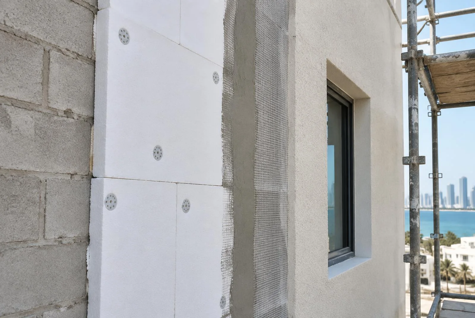
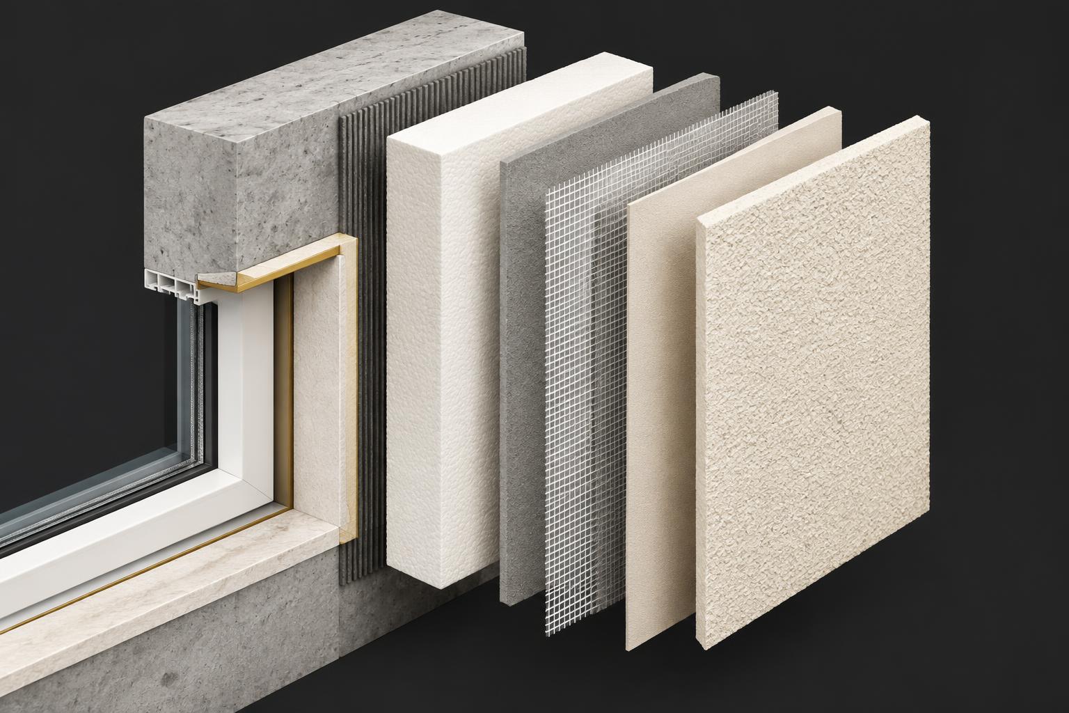
An exterior insulation and finish system (EIFS) is a non-load-bearing exterior wall cladding. In a typical assembly, insulation board is attached to a suitable substrate adhesively and/or mechanically. An integrally reinforced base coat incorporates glass-fibre mesh, and a protective textured finish forms the exposed surface. Adhesives, mechanical fasteners, profiles, accessories and primers are selected within the approved proprietary system; these are not interchangeable parts from an arbitrary catalogue.
EIFS with drainage is a distinct configuration where incidental water is managed by a specified drainage path behind the insulation. Depending on the approved assembly, this can include an air- and water-resistive barrier (AWRB) at the substrate, a drainage plane, continuous insulation, reinforced base coat and finish. The presence, position and detailing of those layers depend on the tested manufacturer system and project requirements; not every EIFS is a drainage assembly.
The chosen system must be considered together with the underlying wall and its exposure. Structural movement, weather and the intended finish affect detailing. A material schedule without approved junctions and inspection stages is an incomplete envelope strategy.
Substrate and readiness
The wall receiving the system must be examined before covering it. Flatness, soundness, dryness and surface condition affect adhesion and alignment. Previous coatings, contaminants, moisture and movement can create problems that are difficult to diagnose once layers conceal the substrate. The approved installation method should define what is acceptable, what needs repair and what requires a different attachment strategy.
Readiness also concerns sequencing: openings, flashings, penetrations and adjacent trades need coordinated details before insulation is fixed. A neat elevation cannot compensate for an unresolved edge condition behind it.
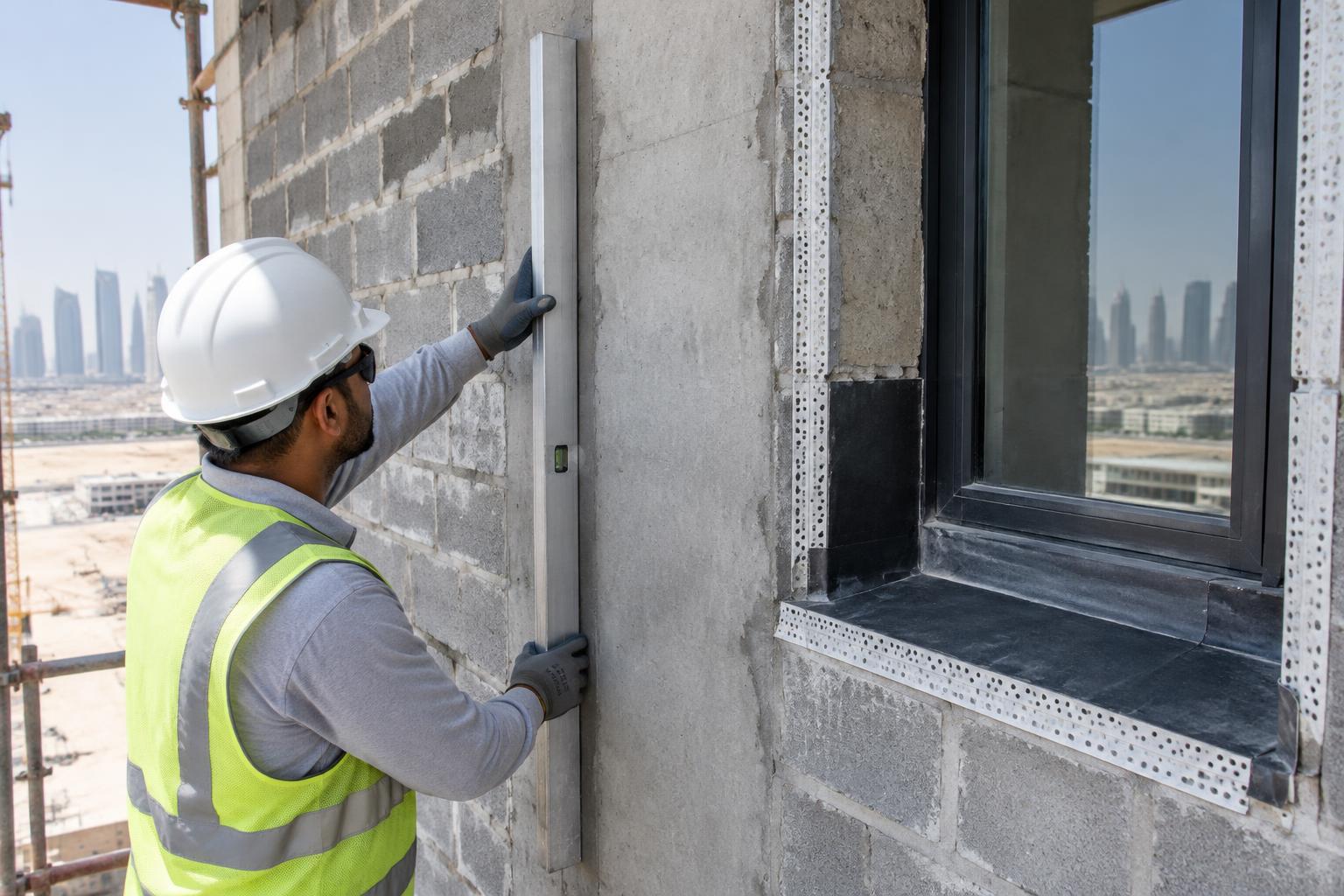
Conditions should be documented before work starts. If the substrate is outside the agreed tolerances, covering it can transfer the problem outward into board alignment and finish appearance. Repairs need review and acceptance rather than improvised compensation with adhesive.
Insulation attachment and continuity
Continuous insulation outside the structural wall can reduce thermal bridges at framing, slab edges and similar junctions. Board joints, pattern, alignment, fixing layout and the treatment of reveals all matter to continuity. Attachment method and board thickness must be determined by the approved assembly, substrate, structural and environmental conditions—not selected by appearance alone.
A wall U-value is a property of the complete construction and its detailing. It cannot be inferred from an insulation-board conductivity figure alone. At corners, parapets and penetrations, thermal, moisture and movement considerations should be resolved together, rather than treated as separate drawing annotations.
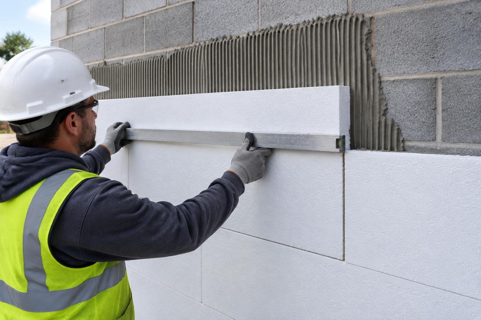
The board layout should limit open gaps and avoid continuous aligned joints where the specified system requires staggering. The calculation of attachment and the treatment of exposed edges must follow the manufacturer and project engineering; visual uniformity is not proof of adequate restraint.
Base coat, mesh and reinforcement
The reinforcing mesh is embedded in the base coat to create a continuous reinforced surface. Coverage, position within the coat, overlap and additional reinforcement at vulnerable corners and openings should follow the approved system details. Mesh exposed at the surface or poorly overlapped is not corrected by adding a decorative finish over it.
Layer thickness and curing conditions affect the result. Inspection points should be established while the underlying work remains visible, before the finish closes access to those details.
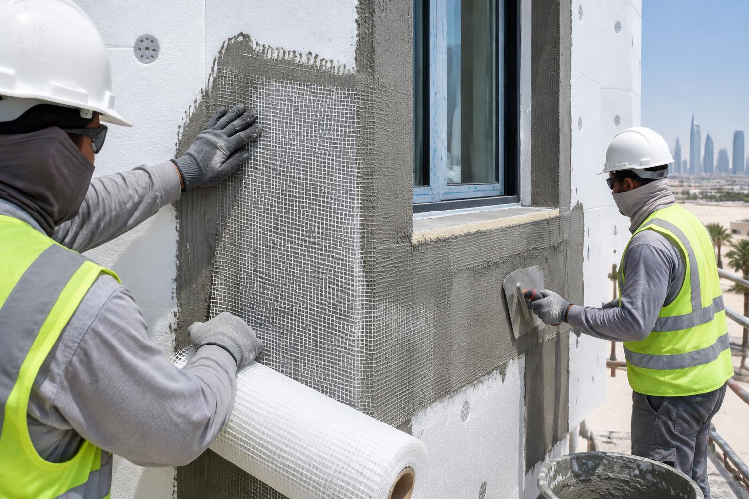
At changes in geometry, reinforcing pieces may be required in addition to the field mesh. Their locations and orientation follow approved details. Teams should inspect these stages before concealment, since a finished elevation offers little visibility into the reinforcement beneath.
Openings, joints and adjacent materials
Window heads, sills and jambs are critical junctions. Water-shedding, sealing, movement accommodation and compatibility with frames and adjacent claddings require project-specific detailing. Movement joints should align with the wall design and system requirements; bridging an intended joint with an uninterrupted finish does not make it disappear.
Fire requirements, termination details, drainage and fastener selection depend on the approved proprietary system, substrate, design conditions, project specification and applicable codes. A detail valid for one assembly should not be copied into another without technical review.
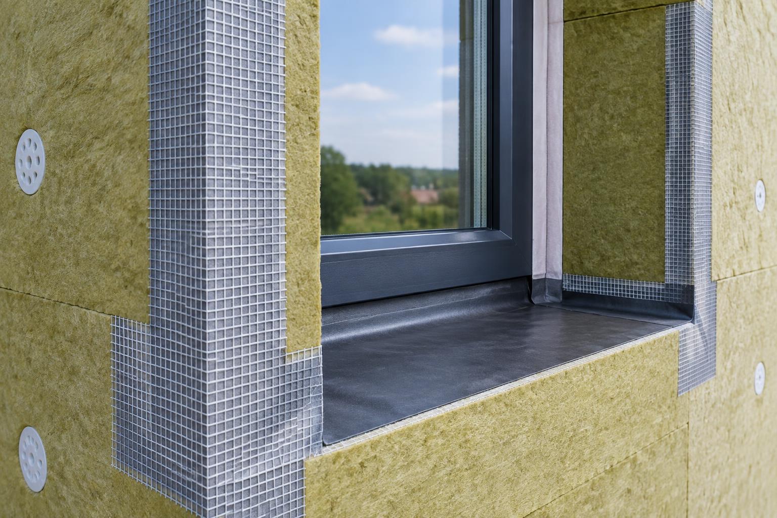
Particular attention belongs at the bottom of walls and around horizontal projections, where runoff and splash-back can challenge detailing. The required drainage and water management approach is determined by the specific system and wall design, not by a generic EIFS label.
Finish, workmanship and inspection
Texture, colour and light can give the façade its architectural character, but visual consistency begins before the finish is applied. Substrate acceptance, fixing patterns, mesh embedment, coat thickness, curing and transitions must be checked against the agreed inspection plan. Site samples can help align expectations about texture, joint expression and colour before broad application.
Quality control is a sequence, not a final glance at the elevation. Record inspections at hold points, protect work from unsuitable application conditions and resolve defects before subsequent layers conceal them. A successful finish is inseparable from the hidden interfaces that support it.
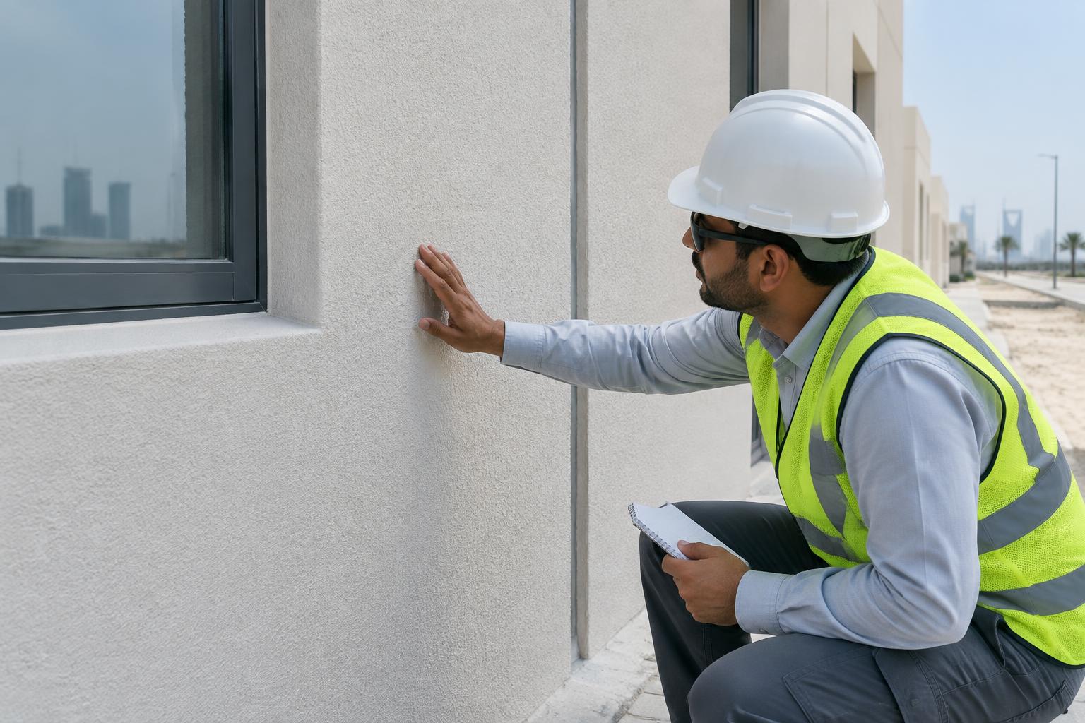
Acceptance should address both appearance and technical records. An agreed sample may establish texture and colour under actual light, while inspection reports establish that concealed layers were checked. Neither substitutes for the other.
KEY TAKEAWAYS
- 01
EIFS is a specified non-load-bearing wall-cladding assembly, not simply a coating.
- 02
Continuous insulation helps address thermal bridges; whole-wall performance depends on the entire construction and its interfaces.
- 03
Drainage, fire, fastening and movement details must follow the particular approved system and applicable codes.